




Add the Timing Components
Add the Timing Components
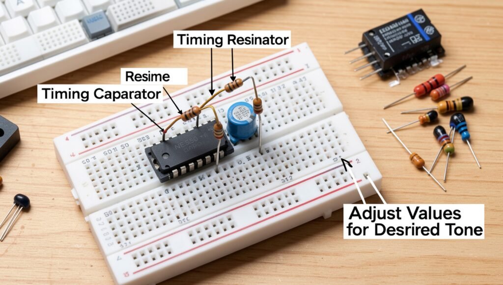
Connect the timing resistors and capacitor to the appropriate pins of the 555 timer to create the timing network that controls the oscillator frequency. In a typical astable 555 configuration, the timing network is connected around Pins 6 (Threshold) and 2 (Trigger), with the resistors connected toward the positive supply and Pin 7 (Discharge). The timing capacitor is connected between the timing node and ground. Follow the circuit diagram carefully because the exact arrangement depends on whether the 555 is configured as an astable, monostable, or another type of circuit.
The values of the resistors and capacitor determine how quickly the capacitor charges and discharges, which in turn controls the frequency of the electrical pulses produced by the 555 timer. For a doorbell circuit, select component values that produce an audible frequency suitable for the buzzer or speaker. For example, changing the resistance or capacitance can make the sound higher or lower in pitch. A larger timing capacitor or resistor generally results in slower oscillation, while smaller values generally produce faster oscillation, within the limits of the circuit.
Carefully install the resistors and capacitor on the breadboard and ensure that every connection is firmly seated. If using a polarized electrolytic capacitor, observe its polarity and connect the negative terminal toward ground as required by the circuit. After assembling the timing network, inspect the wiring for accidental shorts or misplaced connections before applying power. You can later experiment with different resistor and capacitor combinations to fine-tune the oscillator frequency and achieve a pleasant doorbell tone.