




Place the 555 Timer
Place the 555 Timer
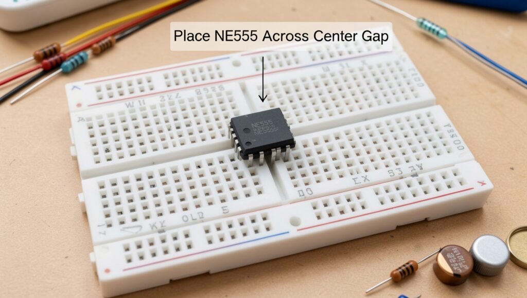
Begin by placing the NE555 timer IC across the center gap of the breadboard. The center gap separates the two sides of the breadboard and allows the pins on opposite sides of the IC to remain electrically isolated from each other. Gently press the IC into position so that one row of pins is on each side of the center channel. Avoid applying excessive force, as the pins can bend or become damaged.
Before making any electrical connections, carefully check the orientation of the 555 timer. Most NE555 ICs have a small semicircular notch or a dot that identifies the pin-1 end. Use this marking to determine the correct pin numbering and compare it with the circuit diagram. For the standard DIP-8 package, Pin 1 is GND, Pin 2 is Trigger, Pin 3 is Output, Pin 4 is Reset, Pin 5 is Control Voltage, Pin 6 is Threshold, Pin 7 is Discharge, and Pin 8 is VCC. Correct orientation is essential because connecting the circuit to the wrong pins can prevent it from working and may potentially damage components.
Once the IC is correctly positioned and oriented, gently press it down until it is securely seated in the breadboard. Do not connect the battery or other power source yet. Keep the surrounding breadboard area organized so there is enough space for the resistors, capacitor, push button, jumper wires, and buzzer or speaker. With the 555 timer correctly positioned, you can proceed to connect the power and timing components according to the circuit diagram.