




Connect the Power
Connect the Power
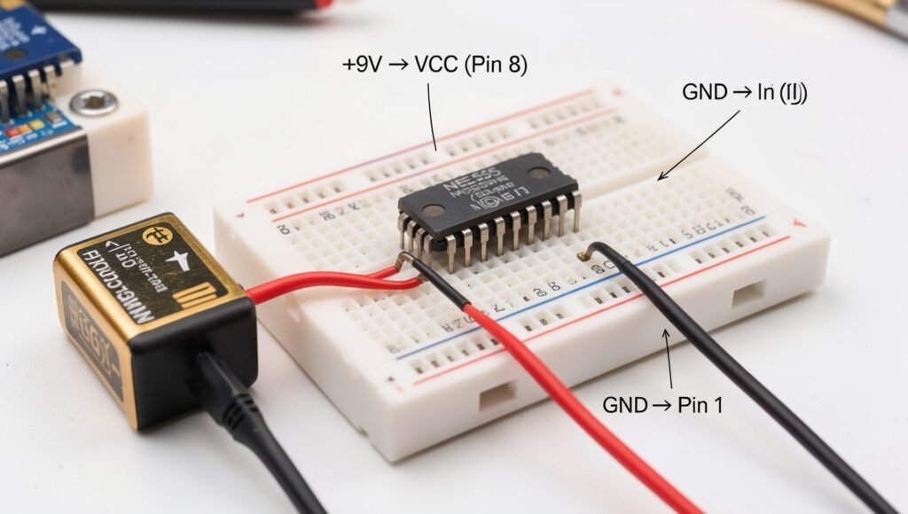
Connect the positive supply rail of the breadboard to the VCC pin (Pin 8) of the 555 timer and connect the ground rail to the GND pin (Pin 1). These two connections provide the operating power required by the timer IC. Make sure the power wires are firmly inserted into the breadboard and that the positive and negative rails are not accidentally shorted together.
A suitable low-voltage DC power source, such as a 9V battery, can be used for a standard bipolar NE555 circuit, provided that the particular IC and other components are rated for the chosen voltage. Connect the battery’s positive terminal to the positive rail and its negative terminal to the ground rail. If using a battery clip, red is normally positive and black is normally negative, but always verify the polarity rather than relying only on wire color. A regulated DC supply may also be used if its voltage is appropriate for the circuit.
Before switching on the power, carefully check the complete circuit against the wiring diagram. Confirm the 555 timer orientation, Pin 8 and Pin 1 connections, battery polarity, and all connections to the timing components, push button, and buzzer or speaker. It is also good practice to place a small bypass capacitor, such as 0.1 µF, between VCC and GND close to the 555 timer to help reduce supply noise and improve circuit stability. Once everything has been verified, connect the battery and proceed to test the doorbell circuit.